Remote Terminal Unit Panel (RTU Panel)

A Remote Terminal Unit (RTU) is a microprocessor-controlled electronic device that interfaces objects in the physical world to a distributed control system or SCADA (supervisory control and data acquisition) system by transmitting telemetry data to a master system, and by using messages from the master supervisory system to control connected objects.
1 Architecture
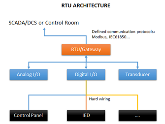
A RTU Panel allows monitors the field digital and analog parameters and transmits data to the Central Monitoring Station. It contains a PLC program
med software to connect data input streams to data output streams, define communication protocols, and troubleshoot installation problems.
A RTU Panel may consist of one complex circuit card consisting of various sections needed to do a custom fitted function or may consist of many circuit cards including CPU or processing with communications interface(s), and one or more of the following: (AI) analog input, (DI) digital input, (DO/CO) digital or control (relay) output, or (AO) analog output card(s).
1.1 Power supply
A form of power supply will be included for operation from the AC mains for various CPU, status wetting voltages and other interface cards. This may consist of AC to DC converters where operated from a station battery system.
1.2 Digital or status inputs
Most RTUs incorporate an input section or input status cards to acquire two state real world information. This is usually accomplished by using an isolated voltage or current source to sense the position of a remote contact (open or closed) at the RTU site. This contact position may represent many different devices, including electrical breakers, liquid valve positions, alarm conditions, and mechanical positions of devices.
1.3 Analog inputs
A RTU can monitor analog inputs of different types including 0-1 mA, 4–20 mA current loop, 0–10 V., ±2.5 V, ±5.0 V etc. Many RTU inputs buffer larger quantities via transducers to convert and isolate real world quantities from sensitive RTU input levels. An RTU can also receive analog data via a communication system from a master or IED (intelligent electronic device) sending data values to it.
The RTU or host system translates and scales this raw data into the appropriate units such as quantity of water left, temperature degrees, or Megawatts, before presenting the data to the user via the human–machine interface.
1.4 Digital (control) outputs
RTUs may drive high current capacity relays to a digital output (or "DO") board to switch power on and off to devices in the field. The DO board switches voltage to the coil in the relay, which closes the high current contacts, which completes the power circuit to the device.
RTUs outputs may also consist of driving a sensitive logic input on an electronic PLC, or other electronic device using a sensitive 5 V input.
1.5 Analog outputs
While not as commonly used, analog outputs may be included to control devices that require varying quantities, such as graphic recording instruments (strip charts). Summed or massaged data quantities may be generated in a master SCADA system and output for display locally or remotely, wherever needed.
1.6 Software and logic control
Modern RTU are usually capable of executing simple programs autonomously without involving the host computers of the DCS or SCADA system to simplify deployment and to provide redundancy for safety reasons.
A RTU in a modern hydropower plant system will consist of startup sequence, stop sequence, emergency stop and interlocking with synchronize device, turbine governor system, excitation system, main inlet valve (MIV), generator switchgear…etc
1.7 Communications
Different communication media (usually serial (RS232, RS485, RS422) or Ethernet). An RTU may support standard protocols (Modbus, IEC 60870-5-101/103/104, DNP3, IEC 60870-6-ICCP, IEC 61850 etc.) to interface any third party software.
Data transfer may be initiated from either end using various techniques to insure synchronization with minimal data traffic. The master may poll its subordinate unit (Master to RTU or the RTU poll an IED) for changes of data on a periodic basis. Analog value changes will usually only be reported only on changes outside a set limit from the last transmitted value. Digital (status) values observe a similar technique and only transmit groups (bytes) when one included point (bit) changes. Another method used is where a subordinate unit initiates an update of data upon a predetermined change in analog or digital data. Periodic complete data transmission must be used periodically, with either method, to insure full synchronization and eliminate stale data. Most communication protocols support both methods, programmable by the installer.
Multiple RTUs or multiple IEDs may share a communications line, in a multi-drop scheme, as units are addressed uniquely and only respond to their own polls and commands.
1.7.1 IED communications
IED communications transfer data between the RTU and an IED. This can eliminate the need for many hardware status inputs, analog inputs, and relay outputs in the RTU. Communications are accomplished by copper or fibre optics lines. Multiple units may share communication lines.
1.7.2 Master communications
Master communications are usually to a larger control system in a control room or a data collection system incorporated into a larger system. Data may be moved using a copper, fibre optic or radio frequency communication system. Multiple units may share communication lines.


